Showing posts with label dc generator. Show all posts

Wednesday 31 January 2018

Types of DC Generator | series dc generator | shunt dc generator | compound dc generator

  No comments
January 31, 2018

DC Generator are classified on the basis of their winding assembling. Means how to stator and armature winding connected it may be series or parallel or both. here you learn and understand Types of DC Generator | series dc generator | shunt dc generator | compound dc generator.


Types of DC Generator with diagram

Generators are classified as follows:
1) Parmanent Magnet DC Generator
2) Sepratly Excited DC Generator
3) Self Excited DC Generator

Self Excited DC Generator are 3 types:
1. Shunt wound generator
2. Series wound generator
3. Compound DC Generator

Compound DC Generator are 2 types:
(1) Short shunt
(2) Long shunt


Detail of the Types of DC Generator | series dc generator | shunt dc generator | compound dc generator:


1) Permanent Magnet DC Generator:
   Parmanent magnet is used for flux.
   (you can read detail we already posted)

2) Sepretly Excited DC Generator:

DC Generator in which field winding is supplied from an external DC source (EX. battery) is called a separately excited DC generator.
Figure shows the connections of a separately excited generator. The voltage output depends upon the speed of rotation of armature and the field current (Eg = φZNP/60 A). Larger the field current and speed, larger is the generated e.m.f.

Separately excited DC generators are rarely used in practice.Normally of self excited type  used.


Armature current, Ia = IL
Terminal voltage, V = Eg - IaRa
Electric power developed = EgIa
Power delivered to load = EgIa - I R = I E - I R = VIa


3) Self Excited DC Generator

3.1) Shunt-Wound DC generator

When the field winding of a generator is connected in parallel with the generator armature, the generator is called a shunt-wound generator .
The excitation current in ashunt-wound generator is dependent upon the output voltage and the field resistance. Normally, field excitation is maintained between 0.5 and 5 percent of the total current output of the generator.


Shunt field current, Ish = V/Rsh
Armature current, Ia = IL + Ish
Terminal voltage, V = Eg - IaRa
Power developed in armature = EgIa
Power delivered to load = VIL


3.2)  Series Wound DC Generator

When the field winding of a DC generator is connected in series with the armature, the generator is called a series-wound generator . The excitation current in a series-wound generator is the same as the current the generator delivers to the load. If the load has a high resistance and only draws a small amount of current, the excitation current is also small. Therefore, the magnetic field of the series field winding is weak, making the generated voltage low.
Conversely, if the load draws a large current, the excitation current is also high. Therefore, the magnetic field of the series field winding is very strong, and the generated voltage is high.


Armature current, Ia = Ise = IL = I
Terminal voltage, V = EG - I(Ra + Rse)
Power developed in armature = EgIa


3.3) Compound DC Generator:

In a compound-wound generator, there are two sets of field windings on each pole - one is in series and the other in parallel with the armature. A compound wound generator may be:

Short Shunt : In which only shunt field winding is in parallel with the armature winding.

Long Shunt : In which shunt field winding is in parallel with both series field and armature winding.


1. Short Shunt Compound DC Generator:


Short shunt
Series field current, Ise = IL
Shunt field current,
Terminal voltage, V = Eg - IaRa - IseRse
Power developed in armature = EgIa


2. Long Shunt Compound DC Generator:


Long shunt
Series field current, Ise = Ia = IL + Ish
Shunt field current, Ish = V/Rsh
Terminal voltage, V = Eg - Ia(Ra + Rse)
Power developed in armature = EgIa
Power delivered to load = VIL


EXTRA: 

In a compound generator the major portion of excitation is usually supplied by the shunt field. The shunt field is slightly weaker and the series field is considerably weaker than those of the corresponding machine in which the entire excitation is produced by a single shunt or a single series winding.

Compound wound generators are of two types:
1) Cumulative wound Generator : In cumulative wound generators the series field assists the shund field

2) Differential wound Generator : In differential wound generators, series field opposes the shunt field.

Read More

Tuesday 30 January 2018

Types of Losses in DC Generator

  No comments
January 30, 2018

There are four internal Types of Losses in DC Generator that decrease efficiency of a DC generator.
1) Copper losses
2) Eddy-current losses
3) Hysteresis losses
4) Mechanical losses

Types of Losses in DC Generator


1) Copper Losses:

Copper loss is the power lost as heat in the windings; it is caused by the flow of current through
the coils of the DC armature or DC field. This loss varies directly with the square of the current
in the armature or field and the resistance of the armature or field coils.

Armature: Ia^2*Ra (armature curent square into armature resistance)

Field: If^2*Rf (field current square into field resistance)


2) Eddy-Current Losses:

As the armature rotates within the field, it cuts the lines of flux at the same time that the copper
coils of wire that are wound on the armature cut the lines of flux. Since the armature is made
of iron, an EMF is induced in the iron, which causes a current to flow. These circulating
currents within the iron core are called eddy-currents

How to reduce:
To reduce eddy-currents, the armature and field cores are constructed from laminated (layered)
steel sheets. The laminated sheets are insulated from one another so that current cannot flow
from one sheet to the other.


3) Hysteresis losses :

Hysteresis losses occur when the armature rotates in a magnetic field. The magnetic domains
of the armature are held in alignment with the field in varying numbers, dependent upon field
strength. The magnetic domains rotate, with respect to the particles not held in alignment, by
one complete turn during each rotation of the armature. This rotation of magnetic domains in
the iron causes friction and heat. The heat produced by this friction is called magnetic hysteresis
loss.

How to reduce:
To reduce hysteresis losses, most DC armatures are constructed of heat-treated silicon steel,
which has an inherently low hysteresis loss. After the heat-treated silicon steel is formed to the
desired shape, the laminations are heated to a dull red and then allowed to cool. This process,
known as annealing, reduces hysteresis losses to a very low value.

4) Mechanical losses :

Rotational or mechanical losses can be caused by bearing friction, brush friction on the
commutator, or air friction (called windage), which is caused by the air turbulence due to
armature rotation. Careful maintenance can be instrumental in keeping bearing friction to a
minimum. Clean bearings and proper lubrication are essential to the reduction of bearing friction.
Brush friction is reduced by assuring proper brush seating, using proper brushes, and maintaining
proper brush tension. A smooth and clean commutator also aids in the reduction of brush
friction.


Read More

Monday 29 January 2018

What is commutator and commutation

  No comments
January 29, 2018

Commutator is the electrical device which perform mechanically conversion of electric current from AC to DC. Commutator is made up of two semi-cylindrical pieces of a smooth conducting material, usually copper, separated by an insulating material.
Commutator Action is called as commutation. Means AC to DC conversion.


Commutation Action : In DC Generator


  • The commutator converts the AC voltage generated in the rotating loop into a DC voltage. It also serves as a means of connecting the brushes to the rotating loop.
  • The purpose of the brushes is to connect the generated voltage to an external circuit. In order to do this, each brush must make contact with one of the ends of the loop.
  • Since the loop or armature rotates, a direct connection is impractical. Instead, the brushes are connected to the ends of the loop through the commutator. which the brushes make contact with each end of the loop.


In a simple one-loop generator, the commutator is made up of two semi-cylindrical pieces of a smooth conducting material, usually copper, separated by an insulating material, as shown in Figure . 

Each half of the commutator segments is permanently attached to one end of the rotating loop, and the commutator rotates with the loop. The brushes, usually made of carbon, rest against the commutator and slide along the commutator as it rotates. This is the means by which the brushes make contact with each end of the loop.


Each brush slides along one half of the commutator and then along the other half. The brushes
are positioned on opposite sides of the commutator; they will pass from one commutator half to
the other at the instant the loop reaches the point of rotation, at which point the voltage that was
induced reverses the polarity.


Every time the ends of the loop reverse polarity, the brushes switch from one commutator segment to the next. This means that one brush is always positive with respect to another.

The voltage between the brushes fluctuates in amplitude (size or magnitude) between zero and some maximum value, but is always of the same polarity (Figure ). In this manner, commutation is accomplished in a DC generator.


One important point to note is that, as the brushes pass from one segment to the other, there is
an instant when the brushes contact both segments at the same time. The induced voltage at this
point is zero. If the induced voltage at this point were not zero, extremely high currents would
be produced due to the brushes shorting the ends of the loop together. The point at which the
brushes contact both commutator segments, when the induced voltage is zero, is called the
"neutral plane."


practical commutator image :


Read More

Working principle of dc generator

  No comments
January 29, 2018

Working principle of dc generator
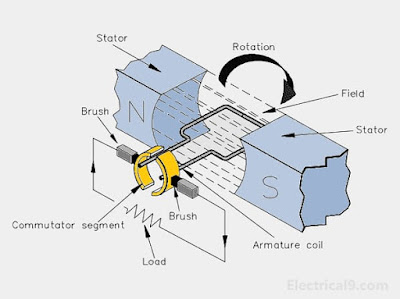
Theory of operation of dc generator and construction and working principle of dc generator.

A basic DC generator has four basic parts:
(1) a magnetic field (2) a single conductor or loop
(3) a commutator and (4) brushes.


working principle of dc generator
A basic DC generator working


working principle of dc generator :
The magnetic field may be supplied by either a permanent magnet or an electromagnet. For now, we will use a permanent magnet to describe a basic DC generator.

A single conductor, shaped in the form of a loop, is positioned between the magnetic poles. As
long as the loop is stationary, the magnetic field has no effect (no relative motion). 

If we rotate the loop, the loop cuts through the magnetic field, and an EMF (voltage) is induced into the loop. When we have relative motion between a magnetic field and a conductor in that magnetic field, and the direction of rotation is such that the conductor cuts the lines of flux, an EMF is induced
into the conductor.

The magnitude of the induced EMF depends on the field strength and the rate at which the flux lines are cut, as given in equation (1).  The stronger the field or the more flux lines cut for a given period of time, the larger the induced EMF.

          Eg = KΦN               ....Equation(1)
 where,
          Eg  =  generated voltage
          K  =  fixed constant
         Φ   =  magnetic flux strength
         N   =  speed in RPM


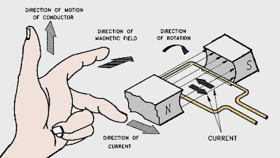
direction of the induced current:

The direction of the induced current flow can be determined using the "left-hand rule" for
generators. This rule states that if you point the index finger of your left hand in the direction
of the magnetic field (from North to South) and point the thumb in the direction of motion of
the conductor, the middle finger will point in the direction of current flow (Figure 2). In the
generator shown in Figure

direction of current in dc generator


Commutation action:

Armature or loop connected to commutator (as shown in image 1).commutator are segments of metal and insulated material provided between each metal segments.Commutator convert AC voltage to DC voltage by mechanically conversion method.
Brushes are attached to both side to commutator to collect generated current and send to output and then supply.   

Read More

Torque-slip characteristic for a three phase induction motor

Relation between torque and slip torque / slip curve is shown in figure: fig. Torque-slip characteristic  For range s=0 to s=1 wit...